
Understanding Alternating Current
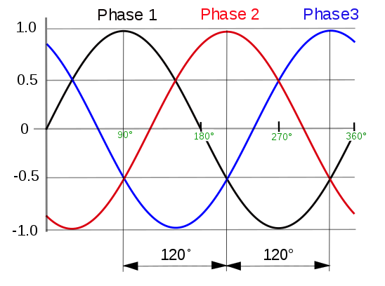
Sine wave alternating current of our homes is produced by a three phase generator. In these generators, three separate coils are present in the generator stator, which is physically offset by an angle of 120° (one-third of a complete 360° phase) to each other. These three phases of generator produce three independent sinusoidal wave of power which offset by 120° with each other. It is also called symmetric three-phase systems.
Source: Wikipedia
In a three-phase system feeding a balanced and linear load, the sum of the instantaneous currents of the three conductors is zero. In other words, the current in each conductor is equal in magnitude to the sum of the currents in the other two, but with the opposite sign. Hence when one of the phase is at maximum positive defection of +1.0, the other two will be the return path of -0.5 each, making the sum of current of the three phase at anytime is zero. This allows less cable use (in compare to a single phase where you need two cable – phase and neutral).
Source: EEP
The sinusoidal waveform is closely related to the coil loops in a magnetic field. At vertical position (0°), the coil do not cut magnetic lines of force, and hence no voltage induced in the loop. When the coil is moving clockwise, it cuts through the magnetic field line and induce positive electric current flow, and increase until it reaches a maximum value when the coil is horizontal to the magnetic lines of force (90°), subsequent rotation clockwise will have negative deflection, at the next vertical position (180°), the voltage is back to zero. Subsequent half cycle clockwise rotation (180° – 360°)will still produce a maximum value like the first half, but opposite polarity due to the coil loop position and the magnetic field polarity is exact opposite to the first half (0° – 180°). These cycle keep repeating, creating the sinusoidal alternating current that we know of.
Irregardless of mechanical source for electricity power generation, either hydro turbine or wind turbine, fossil fuel combustion engine or steam turbine, the generator construction concept is nearly similar. A rotor, coil loop and a magnetic field. The simplicity allows huge and efficient generator to be constructed. The world largest power station is the Three Gorges Dam with thirty two main 700 Mega Watt generator that total up 22,400 Mega Watt production.
One major benefit from a sinusoidal alternating current is the ability to step up and step down easily using transformers. This allows High Voltage Low Current transfer of massive energy via the utility power grid, reducing cost in having smaller power line and reduce energy loss from heat dissipation. Even after few sets of transformer, and long distance traveled, the waveform still remains constantly in phase with the generator.
Sinusoidal alternating current had been long standardize at 50-60 Hertz (Depends on country, those using 50 Hz frequency tend to use 220–240 V, and those that use 60 Hz tend to use 100–127 V) had shaped the development of all modern electronics. Lighting, motors, transformers, generators and transmission lines all have characteristics which depend on the power frequency. Most household Commutator-type induction motors (e.g power tools, home appliance etc) are designed to work with 50-60 Hz. Lower frequency also have advantage of lower impedance losses. Standardization allowed international trade in electrical equipment.
Understanding Waveform of Inverter
The function of an inverter is to change the Direct Current (DC) into Alternating Current (AC). The changes (step up or step down, pure sine wave or modified sine wave etc.) will depends on the inverter specification. One example is a power inverter that takes in 12 Volt DC from your battery and output 230 Volts AC which is similar to the utility power grid.
An inverter can produce a square wave, modified sine wave, pulsed sine wave, pulse width modulated wave (PWM) or sine wave depending on circuit design. The mostly used waveform nowadays is modified sine wave and pure sine wave. This mimics the Alternating Current provided by the power utility grid, allowing easy integrating backup solutions to power common household appliances.
Square Wave Inverter
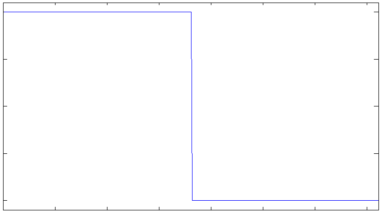
Square wave inverter producing a alternating current which is square in nature. It involves two step, like switching alternatively a positive switch and a negative switch. It is best suited for low-sensitivity applications such as lighting and heating, but not suitable for sensitive electronics and home appliances.
Two level square wave have Total Harmonic Distortion of ~45%.
In a digital era, square wave is not used for a power solution.
Modified Sine Wave Inverter
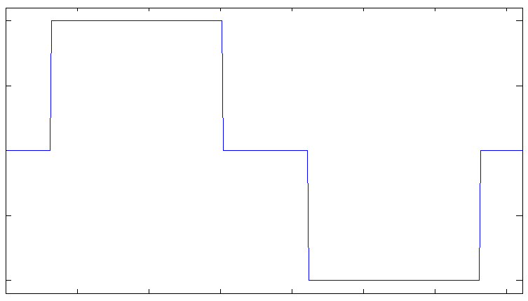
To generate a more closely resemble a sine wave, modified sine wave is similar to a square wave, but adding intervals of zero volts (offs) in between peaks. The waveform results in a three level waveform with equal intervals of zero volts; peak positive volts; zero volts; peak negative volts and then zero volts.
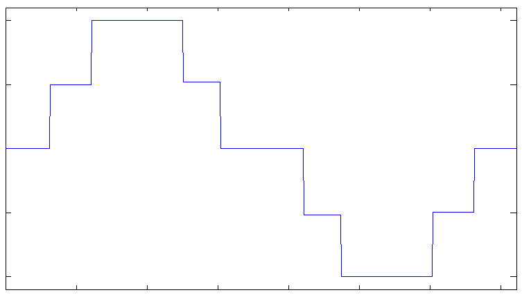
Some modified sine is produce four steps waveform by adding another intermediate voltage between zero and peak voltage, creating a closer resemblance to the actual sinusoidal wave.
Modified sine wave inverter are usually inexpensive and suitable for less sensitive appliances like incandescent bulbs and heater.
However due to the facts that modified sine wave is still not as pure as sine wave from the AC generators, it still can cause problems with sensitive electronics and home appliances. Humming can be heard from audio equipment and AC electric motors for household appliances are found to be running less efficient (due to pulsating torques)and runs hotter. Choppy wave also affects digital devices, controllers with silicon chips and especially those with timing controls. The total harmonic distortion is also high (6.5-23%).
Sine Wave Inverter
Commonly branded as pure sine wave inverter, these consumer grade inverter can produce a alternating current which is very close to a sine wave of the power grid generated by AC generators. The purity is still depends on manufacturer, and often being the most expensive in compared to a modified sine wave inverter.
By adding many steps into the waveform modulation, the waveform will appears to be smooth out. Although under magnification of the wave, there might be minimal choppiness been observed. To further smoothen the waveform, capacitors, inductors, resonant filters and transformers can be used. These addition components increase the cost of the inverter.
This is similar to digital to analog conversion of a audio soundtrack. With more sampling, the resulting analog sound output will be more natural or close to the original source.
Pure sine wave inverter is suitable for sensitive electronics and appliances.
Other use of inverter
The common power inverter convert DC current into AC current with standard frequency at 50-60 Hz. However there are some inverter can varies the frequency output or output at even higher frequency, such as inverter used in air condition compressor and motor in home appliances. Running smooth sine wave at higher frequency can result in more efficient motor (especially brushless and induction motors) control in compare to on-off cycle traditionally.
Power Inverter in a Solar PV system
Unless you are using a single nominal Direct current voltage for all your equipment from solar PV panels, battery, charge controllers and your loads…… you will need some form of inverter to manage the difference in voltage and current requirements between equipment.
Most of the home electrical appliances using common alternating current from power utility grid. These appliances are easily available from local store, in compare to appliances which works with direct currents.
Based on attachment to the grid, there is off grid inverter, grid tie inverter and hybrid inverter. Some of the inverter had been explained in the earlier section at Chapter 6 : Know Your Solar PV System.
Off Grid Inverter
Off grid inverter are simple power inverter that takes in direct current from a battery directly and output alternating current to your loads. They commonly comes in both modified sine wave and pure sine wave variety.
The power range can be as low as a 100 Watt inverter up to 3000-5000 Watt inverter. High wattage inverter will usually works with battery system with higher voltage nominals (e.g. 24-48 volts or more). Lower voltage nominal battery system will result in higher current draw that dissipate allot of energy as heat.
It is important to determine the estimate power draw from your intended loads before hooking up to a inverter. Overloading an inverter will risk overheating and fire. Also handle inverter with care as the voltage output from the inverter is much higher than the battery.
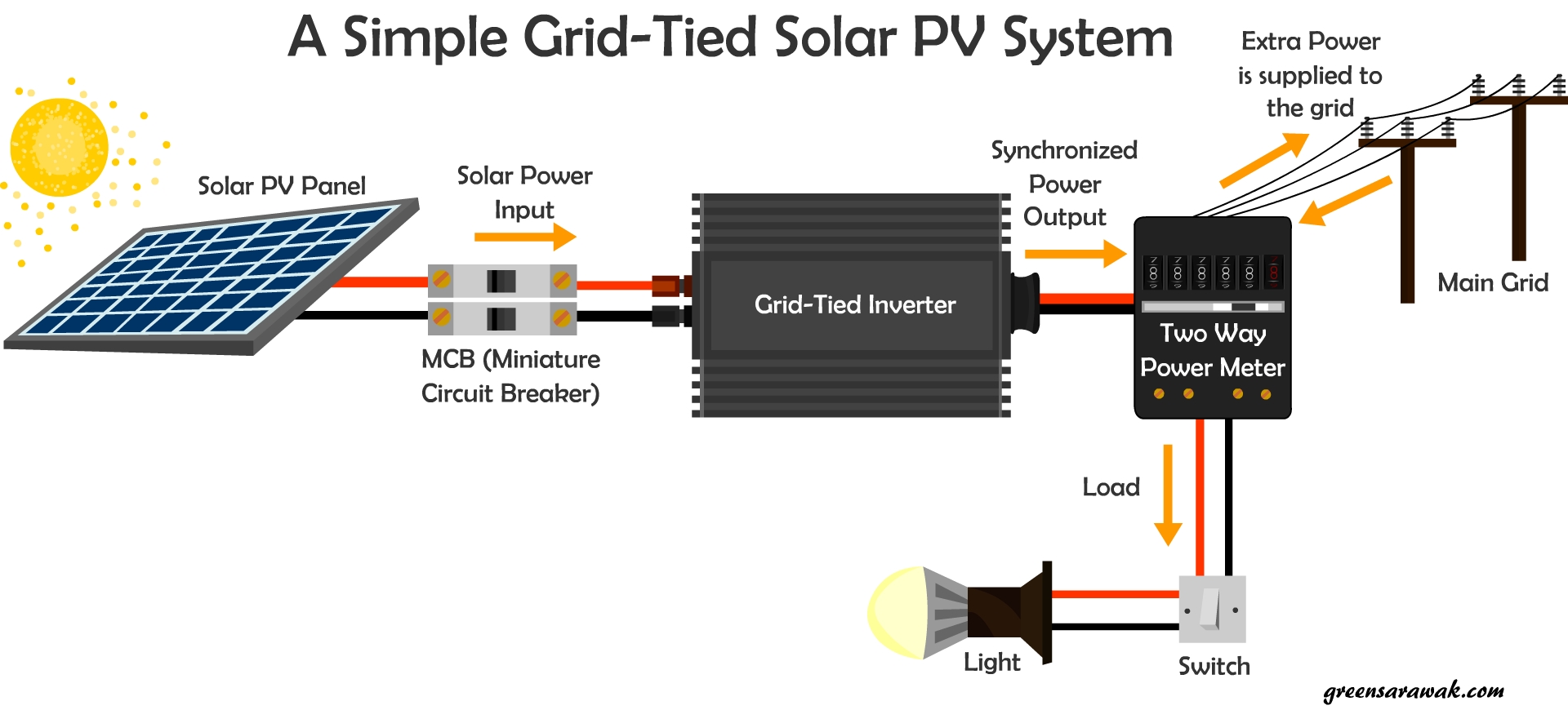
Grid-Tied Inverter
Grid-tied inverter is inverter that takes in direct current from a solar PV panel (either in string or parallel configuration), and output synchronized alternating current into your home power line. This type of inverter is very popular in view of its simplicity and less upfront cost.
Since a slightly higher voltage is supply to the home power line, active home appliance will draw power from the grid tie inverter first before drawing remaining power from the grid. This will reduce the amount of power draw from the grid and hence reduce your monthly electricity bills. In event of excess power from the grid-tie inverter, the excess power will be push back (or sell) to the utility grid. It is called net metering.
However since no battery is added into your system means there is no backup of energy available. With anti-islanding feature mandate by law to prevent electrical accidents to wire repair man during a power outage, the whole systems shuts down when the main power grid is down.
All grid-tied inverter come with Maximum Power Point Tracking (MPPT) to ensure conversion at the highest efficiency.
Grid-tied inverter can come with different power ratings. Depends on your solar PV panel power output you can choose a Grid-Tied inverter with power rating higher than your solar PV panel output to prevent overloading the inverter.
These inverter can be very hot during operation, hence ensure adequate ventilation is available around the inverter.
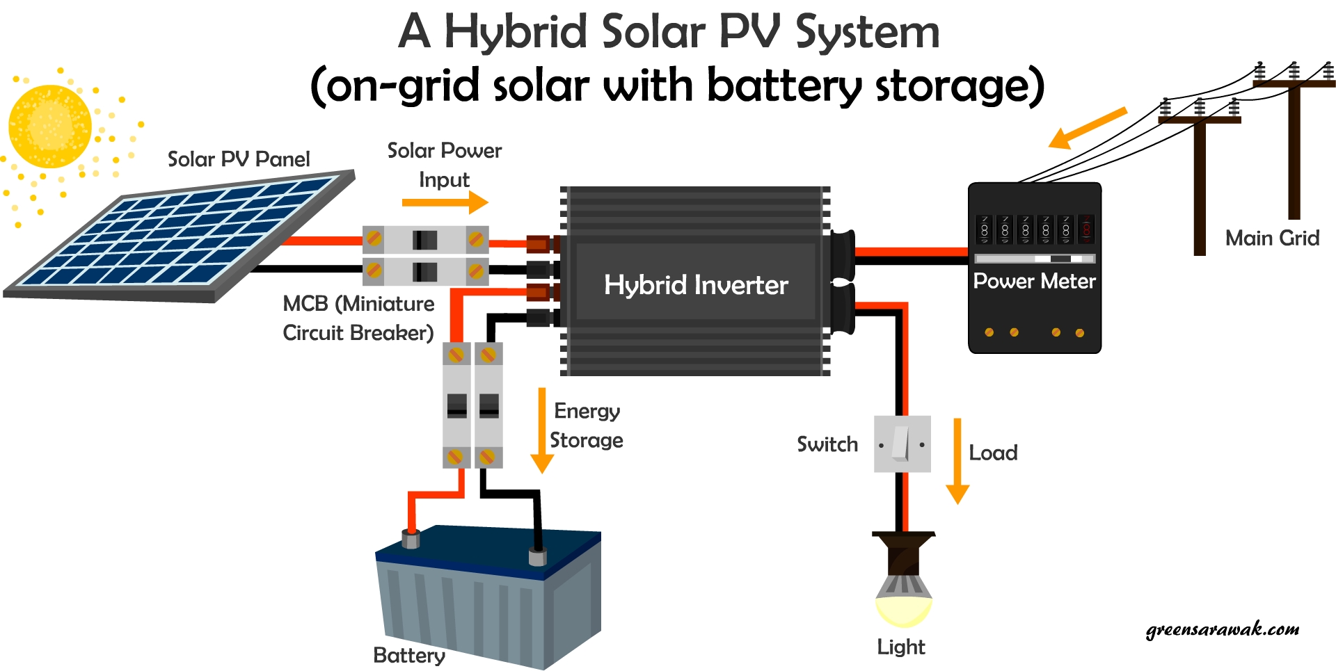
Hybrid Inverters
What if you have a grid tie inverter that sells the extra power to the grid while still have own backup of electricity through a battery system that can allow you to power your critical equipment in event of the down time from the main power grid ? Introducing the Hybrid Inverters or commonly known as on-grid inverter with battery storage. A marriage between a off-grid and on-grid system.
The hybrid inverter is a more advance and intelligent piece of equipment that serve as a guardhouse for all four sector from the power producing solar PV panels, Battery storage system, Connected Home appliances (Load) and the power grid. It is usually comes in high power such as 1KW – 20Kw inverter with micro controllers to control the power transmissions between sectors.
With a advance hybrid inverter, you can set clusters of critical equipment (that should be power on in all times such as refrigerators, computers, network systems, critical lighting etc) which is separated from other non-critical workloads such is TV, Washing machine, Air conditioners, Outdoor Lights etc. Separation of critical and non critical workloads will allow fine tuning of your backup solutions and extend the battery life. It doesn’t protect extended power grid blackouts unless there is secondary power source such as backup generators.
The drawback of this system is the cost. Hybrid solutions is expensive.
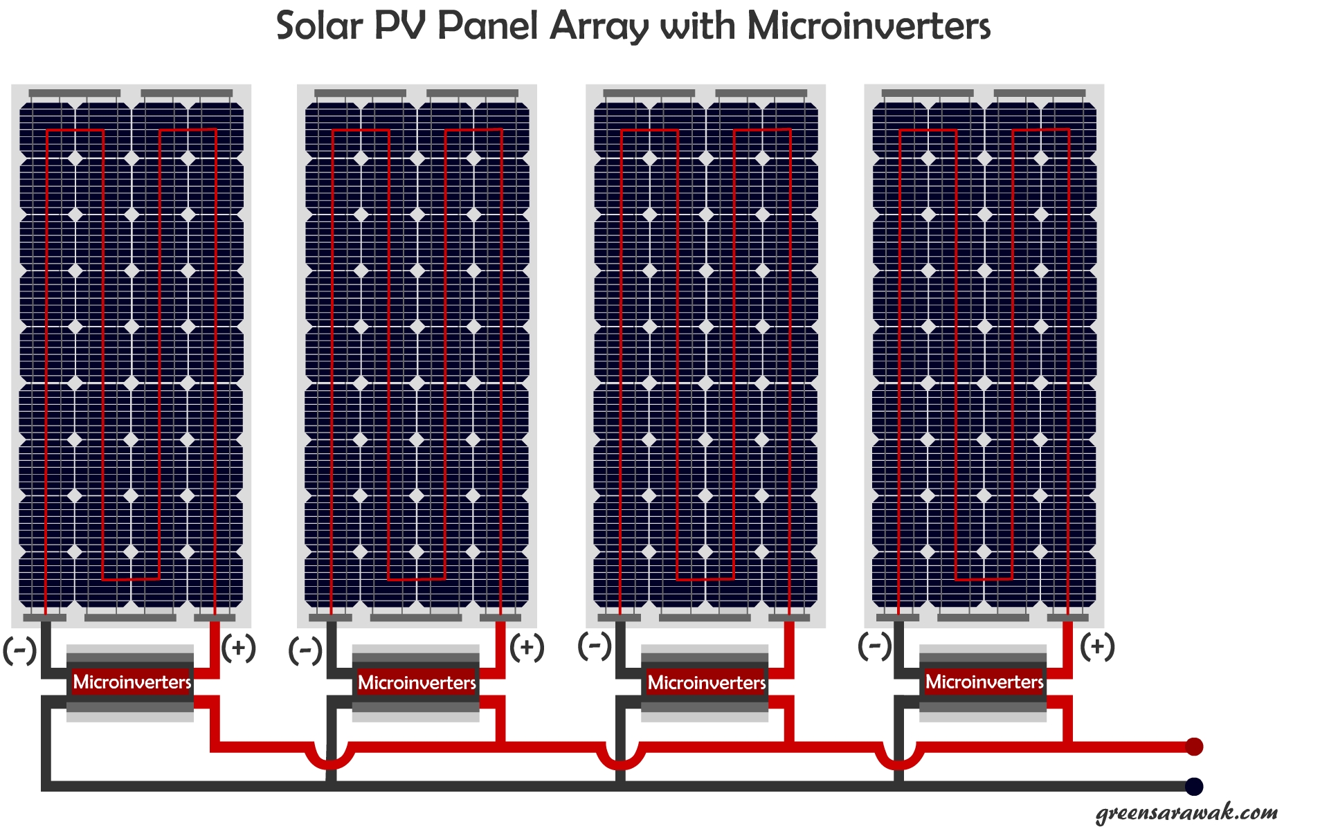
Micro Inverters
Micro Inverters put the entire power conversion system to each panel.
Micro inverters are small inverters that is attached to the back of solar PV panels, or on site inverters which function as a panel level grid tie inverter that is independent on each other. The micro inverters is connect to a common cable that is connected to the power grid.
The main benefit of micro inverters is, panel level optimization. Since each micro inverter is attach to each solar PV panel, hence they can perform at their maximum capacity regardless of the condition of next panel. It is important to note that partial shading of one panel will reduce the efficiency of the whole string in a string inverter.
The effects of partial shading is explained at Chapter 10 : Know the effect of partial shading.
Micro inverters comes with Maximum Power Point Tracking (MPPT) to enhance the efficiency of the solar power generation.
One problem though, since the placement of micro inverters is mostly behind the solar panels, maintenance of faulty micro inverters can be tricky especially on roof top and hard to access areas, where the solar PV panels need to removed first to uncover the Micro Inverters.
Optimizers
Well, if Micro inverters is to convert Direct Current from the solar PV panel output to the Alternating Current that supply the main power grid, then Optimizers are DC to DC converters that have MPPT function to optimize each solar PV panels.
These small devices are connected to solar PV panels to optimize each panel independently with Maximum Power Point Tracking, output constant Direct Current into a common cable that will finally end up with a common inverter. The main benefit of optimizer is to achieve a panel level optimization and reduce effect of partial shading on a solar PV array.
It had better life span than micro inverters due to the fact that the construction of Optimizers are much simpler than Micro inverters. More components, more point of failure. With addition of inverter component in each unit of micro inverters, the cost of equipment raise.
The main conversion of low voltage Direct Current to higher voltage Alternating Current is handle by a Central Inverter in a separate cooler location. Inverters can output a notable amount of heat during active power conversion, which can be 3-6% of the power dissipated as heat. Micro inverters behind a solar PV panel under a hot summer sun will have to suffer more. Yup, the main issue is heat.
Optimizer have greater efficiency 98-99% than Micro inverters 93-96%. However if the efficiency of Optimizer is factor in with its central inverter, it will have slightly dropped due to efficiency of the central inverter itself. Hence efficiency of Micro inverter system and optimizer with central inverter is nearly identical.
However optimizer is not without cons. The output of the optimizer is still subject to cable condition, distance and resistance before reaching the central inverter.
Choosing an Inverter
When choosing an suitable inverter, either a off grid or grid tie inverters, you must always make sure it is compatible to the load you are using. Pay attention to the voltage, amperage and power criteria on the device manufacture spread sheet. Some have a optimum voltage and wattage value while some will state the maximum level it can accept. Overpowered a inverter will risk overheating, fire and early device failure.
Critical components such as integrated circuit, capacitors and mosfets will fail prematurely when encounter higher than recommended voltage or current.
In a off grid system, when an inverter is connected to a battery, ensure the battery can produce enough voltage and current that is stipulated on the inverter. Some battery have different value of sustained amperage draw and peak amperage draw. Draining the battery constantly at its peak current draw will have impact on its lifespan, e.g. sulfaction in flooded lead acid battery.
Remember when the battery is drained, the voltage will get lower and it will need to drain more current to compensate the power conversion.
Load calculation is very important for a off grid inverter. Don’t attach a device that will drain more power than what a inverter can convert. If you have a 1000W device, you need to connect to a inverter that is capable to supply more than 1000W, preferable a 1200Watt and above inverter, if you factor in the conversion efficiency of 85-95%. At high power draw, the inverter will run hotter and hence significant energy loss via heat.
In a grid tie inverter, the output value of the solar PV panels is considered. Important consideration to Voc (Voltage during open circuit) and Isc (Current during short circuit). This will be the value taken as maximum that can be push towards your inverter. In colder regions like winter prone area, extra consideration to have the corrected Voc correlated to temperature to prevent over voltage risk as solar PV panel will produce higher voltage at cooler temperature below standard test condition of 25 degree Celsius.
If you connect the solar PV panels in series, the Voc adds up. If you connect the solar PV panels in parallel, the Isc adds up. Make sure the connected grid tie inverters can handle it.
NEXT CHAPTER >> Know how to monitor your Solar PV power output